Final Design


Early Sketches

To begin the design process, we sat down as a group and began to lay out the functionality that we wanted to achieve throughout the course of this project. On the top right we began to figure out, on the macro scale, where everything was to be placed. On the top left, we started brainstorming about overall dimensions. On the bottom right, we began to focus more on the details. This section included brainstorming and discussing surround each of our modules, where it would be placed, how much space it would take, and what elements we needed to prepare in order to construct the affiliated circuits.
Prototyping and Progress Shots
After a rough layout on paper, we constructed a quick prototype out of cardboard and tape. This allowed us to use a physical model to gain a better spatial understanding of how things fit together. It also helped us solidify the overall dimensions of the box, as well as garner a better understanding of the space allocation for each functional module. As you can see in the associated photos, at this point in the project we had already begun to build some of our smaller circuits. Those we laid out on the bottom of our prototype, giving us an idea of how they would be placed and how long wires would need to be after taking into account service loops for strain relief.
Box Construction
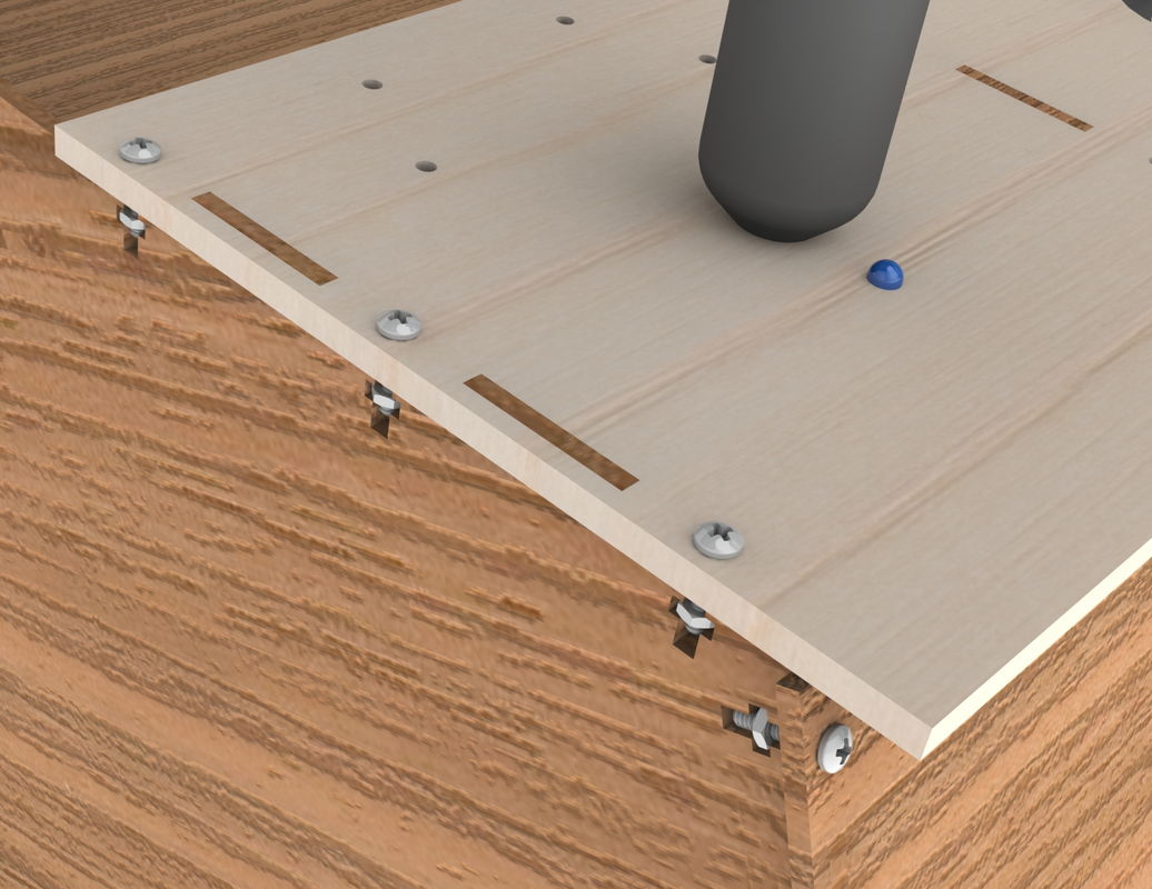
|
The box was constructed using a series of patterned boss/grooves and T-slots. With this strategy, we didn't have to use any adhesives and it allowed us to create robust connections that could still be easily taken apart. This would later allow us to take modules apart in order to debug. With this method of construction, by adding more bolts, we could greatly increase the strength of the frame at the expense of the nuts and bolts themselves. This method also allowed us to easily connect different types of materials together. The main body was constructed out of duron (due to its cheap cost and abundance), the control panel and upper display were made from basswood (for aesthetic purposes) and the kerf bent connection at the top of the box was made of birch (due to its flexibility). |
TOT Insertion
|

|
TOT insertion was designed as a semi-circle with a TOT sized slot cut out of it. This allowed the TOT to roll freely around the semi-circle, only to be captured at the end of the path. A sub-micro servo was placed at the midpoint of the track with its arm occluding the path. Just above the servo on the left is an IR LED, on the right a IR phototransistor. When the TOT is inserted into the top, it rolled along the path until being stopped halfway by the servo arm. In this static position, the TOT broke the beam between the IR LED and the phototransistor. This change in state allowed us to detect the insertion of the TOT. After the game was completed, the servo arm would rotate out of the path of the TOT, freeing it and dispensing it back to the user.
Firestarter Module

|

|
The fire-starter module was designed to resemble the motion made by someone trying to start a fire from two sticks. On the user side, only a small, 3D printed stick protruding from the control panel. This stick has a ¼” D-shaft press fit into the center. This D-shaft ran through a bushing pressed into the control panel and was fixed on either side with shaft collars. The opposite end of the D-shaft was pressed into a paddle-like 3D print that was constrained to about 120 degrees of rotation by two limit switches. When the stick was turned, the paddle rotated in tandem until it bottom out on one of the limit switches resulting in a mechanical stop (and a signal that was read by our game). When rotated back the other direction, the same happened on the other side. In this way, starting a fire and detecting the speed at which the user was starting that fire was simulated.
Fire Oxygenation Module

|
Mechanically, the blowing module was very simple. All that was required was 4 clearance holes for 6-32 screws and nuts to fasten the fan into place. When the fan was blown, it back-drove a voltage that could be read by the game. |
Alien Attack Module
|
The alien attack module consisted mostly of holes cut to the proper size for accommodating LEDs and buttons. The acrylic, however, was more difficult to create. A square cutout was made to increase light dispersion from an LED sub-flush to the control panel. This LED was held by a piece of acrylic that was heat bent into a “U” with a hole to mount the LED in. This was then bonded to the clear, green acrylic backing plate using acrylic cement. The top plate was made using a piece of clear acrylic. A sticker was made in the shape of an alien face and then placed on the acrylic. The piece was then sandblasted to selectively frost the acrylic everywhere except where the sticker was. The sticker was then removed to reveal the clear alien. Into this piece, 4 x 4-40 inserts were heat-set, allowing a bolt to be run through each piece of acrylic as well as the control panel, and screw into the front face, sandwiching everything together. |

|
Fuel Adjustment Module

|
The supply module was constructed out of a servo (mounted with 2 x M2 screws), 5 red LEDs, and a sliding potentiometer (mounted with 2 x M2 screws). A small 3D printed knob was press fit onto the sliding potentiometer to make it more ergonomic for the user. |
Simulation of Fire

The fire LED holder was designed in CAD and 3D printed to hold all of the LEDs used to light the fire at the proper angle. This part was printed on the Form 3, using Draft resin.
